블로그 약 Optimizing LVDS Resistors Boosts Highspeed Data Transfer

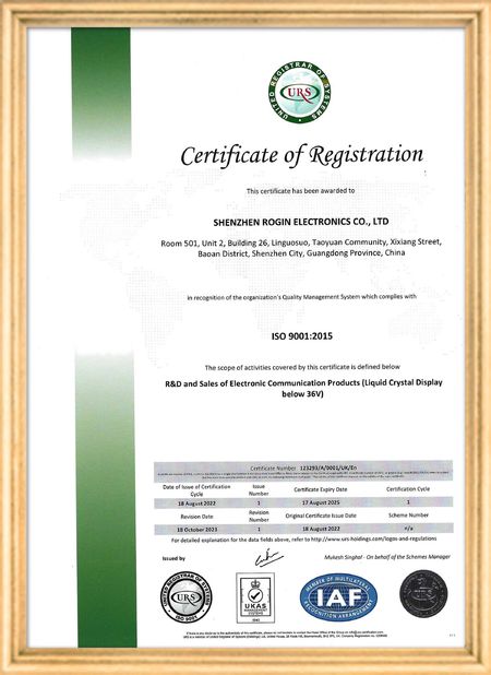
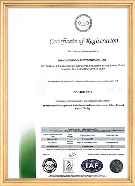
인증
중국 Shenzhen Rogin Electronics Co., Ltd. 인증
고객 검토
이 디스플레이는 전동차에서 완벽하게 작동합니다. 높은 밝기, 반등 방지, 그리고 장기적인 진동에도 안정적입니다. 승객들은 맑은 시야를 좋아합니다.

—— 카스퍼 소렌센

정확한 색상, 빠른 반응, 정상적인 낮은 온도 시작

—— 니콜 베커

쉬운 설치, 넓은 온도 범위, 밝은 환경에서의 뛰어난 가시성. 이 디스플레이는 당사의 모든 산업 장비 요구 사항을 충족합니다.

—— 조반니

이 높은 밝기의 LCD는 산업용 제어판에 적합합니다. 그들은 직접적인 작업실 햇빛 아래에도 결정적으로 맑고 문제없이 24/7 작동합니다..

—— 루카스 뮬러

제가 지금 온라인 채팅 해요
회사 블로그
Optimizing LVDS Resistors Boosts Highspeed Data Transfer
에 대한 최신 회사 뉴스 Optimizing LVDS Resistors Boosts Highspeed Data Transfer
Are you ready for a speed revolution? Imagine your data traveling like lightning across circuit boards, breaking through performance barriers. But beware—without proper termination, your valuable data could suffer catastrophic collisions, signal reflections, and corruption that could cripple your system's performance.
LVDS: The Ultimate Solution for High-Speed Data Transfer

In today's data-driven world, Low-Voltage Differential Signaling (LVDS) technology has emerged as the industry leader, prized by engineers for its exceptional noise immunity and high-speed transmission capabilities. However, unlocking LVDS's full potential requires mastering one critical component: the art of termination resistors.

Why LVDS Outperforms Single-Ended Signaling:
  • Blazing Speed: With a low voltage swing (approximately 350mV), LVDS achieves significantly faster rise and fall times, enabling unprecedented data rates.
  • Robust Noise Immunity: The differential signaling architecture provides superior common-mode noise rejection, maintaining signal integrity even in electrically noisy environments.
  • Enhanced EMC Performance: Differential signals generate opposing electromagnetic fields that largely cancel out, reducing interference with nearby systems.
Termination Resistors: The Guardians of Signal Integrity

In high-speed transmission systems, impedance mismatches can cause destructive signal reflections that distort waveforms and degrade performance. Termination resistors serve as energy absorbers at transmission line ends, preventing these reflections by matching the line's characteristic impedance.

For LVDS systems using 100Ω differential cables (such as twisted pairs), a 100Ω termination resistor at the receiver input creates the perfect impedance match—the key to optimal signal transmission.

Case Study: Termination Resistance Impact on Signal Quality

Simulation analysis using LTC6754 comparators demonstrates the dramatic effects of termination resistance. When using the correct 100Ω termination:

  • Receiver signals maintain clean, stable waveforms
  • Signal integrity remains uncompromised

With improper termination (50Ω or 200Ω):

  • Significant waveform distortion occurs
  • Reflections corrupt the signal
  • Data reliability suffers
LVDS System Components
Drivers and Receivers: The Dynamic Duo

LVDS systems rely on complementary components:

  • Drivers: Convert data to LVDS signals using current-source output structures (typically ±3.5mA current through 100Ω termination produces 350mV differential voltage)
  • Receivers: Detect small differential voltages with high input impedance and sensitivity, converting them back to digital logic levels
Common-Mode Voltage: The Balancing Act

LVDS specifications require the average voltage of differential pairs (common-mode voltage) to remain between 1.125V and 1.375V. Mismatched common-mode voltages between drivers and receivers can cause signal degradation.

Transmission Line Fundamentals

Understanding transmission line theory is essential for high-speed design. Transmission lines exhibit distributed inductance (L) and capacitance (C), with characteristic impedance (Z₀) calculated as:

Z₀ = √(L/C)

Impedance matching between source, transmission line, and load prevents signal reflections.

Simulation Tools for Design Optimization
  • Lossless (TLINE): Idealized analysis
  • Lossy (LTLINE): Real-world modeling including losses
Implementation Recommendations
  • Always match termination resistance to transmission line impedance (typically 100Ω for LVDS)
  • Verify common-mode voltage compliance (1.125V–1.375V range)
  • Utilize simulation tools to analyze signal behavior before implementation
  • Consult application notes (e.g., AN-1177 LVDS/M-LVDS Implementation Guide) for design details

By following these guidelines, engineers can harness LVDS technology to achieve reliable, high-speed data transmission across numerous applications including display interfaces, data communications, and imaging systems.

선술집 시간 : 2026-05-17 00:00:00 >> blog list
연락처 세부 사항
Shenzhen Rogin Electronics Co., Ltd.

담당자: Mr. Kelvin Zhu

전화 번호: +86 15919061504

회사에 직접 문의 보내기 (0 / 3000)